How to commission WDM TDM Board Interfaces?
This section describes how to commission the TDM interfaces of WDM network boards.
Prerequisites
Checking the hardware has been completed, the router device to be commissioned is running properly, the E1 cables on the AC sides for carrying TDM services are correctly connected, and network-side cables are connected correctly.
Context
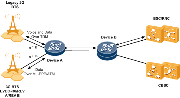
As shown in below figure, a static routing protocol has to be deployed in the network to ensure normal communication between the DeviceA device and the network segment 172.16.1.0 where the DeviceB is located.
Typical networking diagram for TDM interface commissioning
Procedure
- Configure a TDM serial interface and specify the protocol of the interface as TDM. The following uses serial interface 2/0/0:1 as an example to describe how to configure a TDM serial interface.
- Configure a TDM PWE3 service for the serial interface.
For the detailed procedure, see the guides to configure TDM services for router devices. Then run the display this command on the router device to view the configurations of the serial interface.
[HUAWEI-Serial2/0/0:1] display this # interface Serial2/0/0:1 link-protocol tdm mpls l2vc 2.2.2.2 pw-template 1 101 # return
On the device, use the same way to configure a TDM PWE3 service for the serial interface. Ensure that the PW profile parameters of the device are same.
- On the router device, run the display mpls l2vc command to check the status of the TDM PW.
[HUAWEI] display mpls l2vc inter serial 2/0/0:1 *client interface : Serial2/0/0:1 is up Administrator PW : no session state : up AC status : up VC state : up Label state : 0 Token state : 0 VC ID : 101 VC type : CESoPSN basic mode destination : 2.2.2.2 local group ID : 0 remote group ID : 0 local VC label : 16 remote VC label : 20 local TDM Encap Num : 8 remote TDM Encap Num : 8 jitter-buffer : 4 local rtp-header : disable remote rtp-header : disable local bit-rate : 31 remote bit-rate : 31 local AC OAM State : up local PSN OAM State : up local forwarding state : forwarding local status code : 0x0 remote AC OAM state : up remote PSN OAM state : up remote forwarding state: forwarding remote status code : 0x0 ignore standby state : no BFD for PW : unavailable VCCV State : up manual fault : not set active state : active forwarding entry : exist OAM Protocol : -- OAM Status : -- OAM Fault Type : -- PW APS ID : 0 PW APS Status : -- TTL Value : 1 link state : up local VC MTU : -- remote VC MTU : -- local VCCV : alert ttl lsp-ping bfd remote VCCV : alert ttl lsp-ping bfd local control word : disable remote control word : disable tunnel policy name : tp31 PW template name : 1 primary or secondary : primary load balance type : flow Access-port : false Switchover Flag : false VC tunnel/token info : 1 tunnels/tokens NO.0 TNL type : cr lsp, TNL ID : 0x3 Backup TNL type : lsp , TNL ID : 0x0 create time : 0 days, 4 hours, 42 minutes, 2 seconds up time : 0 days, 0 hours, 3 minutes, 59 seconds last change time : 0 days, 0 hours, 3 minutes, 59 seconds VC last up time : 2014/11/28 14:44:27 VC total up time : 0 days, 0 hours, 3 minutes, 59 seconds CKey : 2 NKey : 1 PW redundancy mode : frr AdminPw interface : -- AdminPw link state : -- Diffserv Mode : pipe Service Class : ef Color : green DomainId : -- Domain Name : --
As shown in the command output, the interface configurations and cable connections are correct, no alarms are reported for the interface, and the PW is up. In addition, after a test instrument feeds a service to the router device, the service is transmitted properly.
Handling Common Faults
The PW profile parameters of the router device are inconsistent.Handling procedure:Run the display pw-template command on the router device to check whether the PW profile parameters are consistent. If they are inconsistent, make changes properly to make them consistent.
<HUAWEI> display pw-template PW Template Name : 1 PeerIP : -- Tnl Policy Name : -- CtrlWord : Disable MTU : 1500 Max Atm Cells : 28 ATM Pack Overtime: 1000 Seq-Number : Disable TDM Encapsulation Number: 8 Jitter-Buffer : 4 Rtp-Header : Disable VCCV Capability : alert ttl lsp-ping bfd Behavior Name : -- Total PW : 0, Static PW : 0, LDP PW : 0
The AC-side interfaces that carry TDM services are not up. These interfaces include the E1 and serial interfaces.- Handling procedure 1:
- In the E1 interface view, run the display this interface command to check whether the physical state of the interface is up. If the state is not up, handle the fault of the E1 interface being down.
- In the serial interface view, run the display this interface command to check whether the serial interface has been shut down. If the serial interface has been shut down, run the undoshut serial command to turn on the interface.
- In the serial interface view, run the display this command separately on the router device to check whether the TDM protocol is used on the two devices. If it is not, correct the setting to ensure that the two devices use the TDM protocol.
[HUAWEI-Serial2/0/0:1] display this # interface Serial2/0/0:1 link-protocol tdm mpls l2vc 2.2.2.2 pw-template 1 101 # return
For the E1 interfaces on the router device, the channelized mode or the number of bound timeslots differs.- Handling procedure:
- In the E1 interface view, run the display this command on the router device to view the channelized mode and number of bound timeslots configured for the E1 interfaces. If the configurations are inconsistent, correct them.
[HUAWEI-E1 2/0/0] display this # controller E1 2/0/0 channel-set 1 timeslot-list 1-31 undo shutdown # return An example is as follows: [PPP_980B-E1 2/0/1]display this # controller E1 2/0/1 using e1 undo shutdown # return
The PW or tunnel that carries the TDM service is down.Handling procedure: On the router device, run the display mpls l2vc ommand to check the PW status of the port where the service is interrupted.
[HUAWEI] display mpls l2vc inter serial 2/0/0:1 *client interface : Serial2/0/0:1 is up Administrator PW : no session state : up AC status : up VC state : down Label state : 0 Token state : 0 VC ID : 101 VC type : CESoPSN basic mode destination : 2.2.2.2 local group ID : 0 remote group ID : 0 local VC label : 16 remote VC label : 22 local TDM Encap Num : 8 remote TDM Encap Num : 8 jitter-buffer : 4 local rtp-header : disable remote rtp-header : disable local bit-rate : 1 remote bit-rate : 1 local AC OAM State : up local PSN OAM State : up local forwarding State : forwarding local status code : 0x0 remote AC OAM State : up remote PSN OAM State : up remote forwarding State: not forwarding remote status code : 0x1 ignore standby state : no BFD for PW : unavailable VCCV state : no manual fault : no set active state : inactive forwarding entry : not exist OAM Protocol : -- OAM Status : -- OAM Fault Type : -- PW APS ID : 0 PW APS Status : -- PW APS Status : -- TTL Value : 1 link state : down local VC MTU : 2000 remote VC MTU : 0 local VCCV : cw alert ttl lsp-ping bfd remote VCCV : cw alert ttl lsp-ping bfd local control word : enable remote control word : enable tunnel policy name : -- PW template name : 1 primary or secondary : primary load balance type : flow Access-port : false Switchover Flag : false VC tunnel/token info : 1 tunnels/tokens NO.0 TNL type : lsp , TNL ID : 0x2 Backup TNL type : lsp , TNL ID : 0x0 create time : 0 days, 1 hours, 9 minutes, 32 seconds up time : 0 days, 0 hours, 0 minutes, 0 seconds last change time : 0 days, 1 hours, 9 minutes, 32 seconds VC last up time : 0000/00/00 00:00:00 VC total up time : 0 days, 0 hours, 0 minutes, 0 seconds CKey : 4 NKey : 3 PW redundancy mode : frr AdminPw interface : -- AdminPw link state : -- Diffserv Mode : pipe Service Class : ef Color : green DomainId : -- Domain Name : --
- If the AC status is displayed as down in the command output, see the fault handling procedure for cause 3. If the session state is displayed as down, handle the fault by referring to the MPLS fault handling procedure.
- If the AC status and the session state are displayed as up but the VC is down, check whether the VC ID, VC type, and control word of the router device are same .
- If they are inconsistent, make changes properly to make them consistent. If they are consistent but the VC is down, handle the fault by referring to the tunnel fault handling procedure.
Handling procedure 2:- Check whether the QoS is configured for the network interface. If QoS is configured, handle the fault by referring to the QoS fault handling procedure.
- If the physical state of the TDM link is displayed as *down, then the serial interface has been shut down manually. Enter the serial interface view and run the undo shutdown command.
- If the physical state of the TDM link is displayed as down, then the E1 line is faulty. Handle the fault by referring to the E1 fault handling procedure.
The bandwidth allocated to the TDM service on the NNI side is insufficient, or the service packets of a higher priority occupied the bandwidth allocated to the TDM service.Handling procedure:- Check whether the QoS is configured for the network interface. If QoS is configured, handle the fault by referring to the QoS fault handling procedure.
- Check whether the bandwidth on the NNI side is sufficient for transmitting the TDM service. For example, if n timeslots have been configured for the TDM service, calculate the bandwidth required by one TDM service using the following formula: TDM service bandwidth = n x 8 x 8000/8 + Length of the Ethernet packet header.
Comments
There are no comments yet