I need to monitor NAT and PAT. Can someone help me?
This section describes how to configure network object NAT for dynamic PAT (hide). For more information, see the “Dynamic PAT” section.
For a PAT pool:
For extended PAT for a PAT pool:
For round robin for a PAT pool:
Purpose
Step 1
(Optional) Create a network object or group for the mapped addresses.
See the “Adding Network Objects for Mapped Addresses” section.
Step 2
object network obj_name
ciscoasa(config)# object network my-host-obj1
Configures a network object for which you want to configure NAT, or enters object network configuration mode for an existing network object.
Step 3
{ host ip_address | subnet subnet_address netmask | range ip_address_1 ip_address_2 }
ciscoasa(config-network-object)# range 10.1.1.1 10.1.1.90
If you are creating a new network object, defines the real IP address(es) (either IPv4 or IPv6) that you want to translate.
Step 4
nat [ ( real_ifc , mapped_ifc ) ] dynamic { mapped_inline_host_ip | mapped_obj | pat-pool mapped_obj [ round-robin ] [ extended ] [ flat [ include-reserve ]] | interface [ ipv6 ]} [ interface [ ipv6 ]] [ dns ]
ciscoasa(config-network-object)# nat (any,outside) dynamic interface
Configures dynamic PAT for the object IP addresses. You can only define a single NAT rule for a given object. See the “Additional Guidelines” section.
See the following guidelines:
– An existing network object that is defined as a host address (see Step 1).
– pat-pool —An existing network object or group that contains multiple addresses.
– interface —(Routed mode only) The IP address of the mapped interface is used as the mapped address. If you specify ipv6 , then the IPv6 address of the interface is used. For this option, you must configure a specific interface for the mapped_ifc . You must use this keyword when you want to use the interface IP address; you cannot enter it inline or as an object.
– Round robin—The round-robin keyword enables round-robin address allocation for a PAT pool. Without round robin, by default all ports for a PAT address will be allocated before the next PAT address is used. The round-robin method assigns an address/port from each PAT address in the pool before returning to use the first address again, and then the second address, and so on.
(continued)
– Extended PAT—The extended keyword enables extended PAT. Extended PAT uses 65535 ports per service , as opposed to per IP address, by including the destination address and port in the translation information. Normally, the destination port and address are not considered when creating PAT translations, so you are limited to 65535 ports per PAT address. For example, with extended PAT, you can create a translation of 10.1.1.1:1027 when going to 192.168.1.7:23 as well as a translation of 10.1.1.1:1027 when going to 192.168.1.7:80.
– Flat range—The flat keyword enables use of the entire 1024 to 65535 port range when allocating ports. When choosing the mapped port number for a translation, the ASA uses the real source port number if it is available. However, without this option, if the real port is not available, by default the mapped ports are chosen from the same range of ports as the real port number: 1 to 511, 512 to 1023, and 1024 to 65535. To avoid running out of ports at the low ranges, configure this setting. To use the entire range of 1 to 65535, also specify the include-reserve keyword.
The following example configures dynamic PAT that hides the 192.168.2.0 network behind address 10.2.2.2:
ciscoasa(config-network-object)# subnet 192.168.2.0 255.255.255.0
ciscoasa(config-network-object)# nat (inside,outside) dynamic 10.2.2.2
The following example configures dynamic PAT that hides the 192.168.2.0 network behind the outside interface address:
ciscoasa(config)# object network my-inside-net
ciscoasa(config-network-object)# nat (inside,outside) dynamic interface
The following example configures dynamic PAT with a PAT pool to translate the inside IPv6 network to an outside IPv4 network:
ciscoasa(config)# object network IPv4_POOL
ciscoasa(config-network-object)# range 203.0.113.1 203.0.113.254
ciscoasa(config)# object network IPv6_INSIDE
ciscoasa(config-network-object)# subnet 2001:DB8::/96
ciscoasa(config-network-object)# nat (inside,outside) dynamic pat-pool IPv4_POOL
This section describes how to configure a static NAT rule using network object NAT. For more information, see the “Static NAT” section.
ciscoasa(config-network-object)# subnet 10.2.1.0 255.255.255.0
If you are creating a new network object, defines the real IP address(es) (IPv4 or IPv6) that you want to translate.
nat [ ( real_ifc , mapped_ifc ) ] static { mapped_inline_ip | mapped_obj | interface [ ipv6 ]} [ net-to-net ] [ dns | service { tcp | udp } real_port mapped_port ] [ no-proxy-arp ]
ciscoasa(config-network-object)# nat (inside,outside) static MAPPED_IPS service tcp 80 8080
Configures static NAT for the object IP addresses. You can only define a single NAT rule for a given object.
– An existing network object or group (see Step 1).
– interface —(Static NAT-with-port-translation only; routed mode) For this option, you must configure a specific interface for the mapped_ifc . If you specify ipv6 , then the IPv6 address of the interface is used. Be sure to also configure the service keyword.
Typically, you configure the same number of mapped addresses as real addresses for a one-to-one mapping. You can, however, have a mismatched number of addresses. See the “Static NAT” section.
The following example configures static NAT for the real host 10.1.1.1 on the inside to 10.2.2.2 on the outside with DNS rewrite enabled.
ciscoasa(config-network-object)# host 10.1.1.1
ciscoasa(config-network-object)# nat (inside,outside) static 10.2.2.2 dns
The following example configures static NAT for the real host 10.1.1.1 on the inside to 10.2.2.2 on the outside using a mapped object.
ciscoasa(config)# object network my-mapped-obj
ciscoasa(config-network-object)# host 10.2.2.2
ciscoasa(config-network-object)# object network my-host-obj1
ciscoasa(config-network-object)# nat (inside,outside) static my-mapped-obj
The following example configures static NAT-with-port-translation for 10.1.1.1 at TCP port 21 to the outside interface at port 2121.
ciscoasa(config)# object network my-ftp-server
ciscoasa(config-network-object)# nat (inside,outside) static interface service tcp 21 2121
The following example maps an inside IPv4 network to an outside IPv6 network.
ciscoasa(config)# object network inside_v4_v6
ciscoasa(config-network-object)# subnet 10.1.1.0 255.255.255.0
ciscoasa(config-network-object)# nat (inside,outside) static 2001:DB8::/96
The following example maps an inside IPv6 network to an outside IPv6 network.
ciscoasa(config)# object network inside_v6
ciscoasa(config-network-object)# subnet 2001:DB8:AAAA::/96
ciscoasa(config-network-object)# nat (inside,outside) static 2001:DB8:BBBB::/96
This section describes how to configure an identity NAT rule using network object NAT. For more information, see the “Identity NAT” section.
(Optional) Create a network object for the mapped addresses.
The object must include the same addresses that you want to translate. See the “Adding Network Objects for Mapped Addresses” section.
Configures a network object for which you want to perform identity NAT, or enters object network configuration mode for an existing network object. This network object has a different name from the mapped network object (see Step 1) even though they both contain the same IP addresses.
If you are creating a new network object, defines the real IP address(es) (IPv4 or IPv6) to which you want to perform identity NAT. If you configured a network object for the mapped addresses in Step 1, then these addresses must match.
nat [ ( real_ifc , mapped_ifc ) ] static { mapped_inline_ip | mapped_obj } [ no-proxy-arp ] [ route-lookup ]
ciscoasa(config-network-object)# nat (inside,outside) static MAPPED_IPS
Configures identity NAT for the object IP addresses.
Note You can only define a single NAT rule for a given object. See the “Additional Guidelines” section.
– Inline IP address—The netmask or range for the mapped network is the same as that of the real network. For example, if the real network is a host, then this address will be a host address. In the case of a range, then the mapped addresses include the same number of addresses as the real range. For example, if the real address is defined as a range from 10.1.1.1 through 10.1.1.6, and you specify 10.1.1.1 as the mapped address, then the mapped range will include 10.1.1.1 through 10.1.1.6.
The following example maps a host address to itself using an inline mapped address:
ciscoasa(config-network-object)# nat (inside,outside) static 10.1.1.1
The following example maps a host address to itself using a network object:
ciscoasa(config)# object network my-host-obj1-identity
ciscoasa(config-network-object)# nat (inside,outside) static my-host-obj1-identity
By default, all TCP PAT traffic and all UDP DNS traffic uses per-session PAT. To use multi-session PAT for traffic, you can configure per-session PAT rules: a permit rule uses per-session PAT, and a deny rule uses multi-session PAT. For more information about per-session vs. multi-session PAT, see the “Per-Session PAT vs. Multi-Session PAT” section.
By default, the following rules are installed:
xlate per-session permit tcp any4 any6
xlate per-session permit tcp any6 any4
xlate per-session permit tcp any6 any6
xlate per-session permit udp any4 any4 eq domain
xlate per-session permit udp any4 any6 eq domain
xlate per-session permit udp any6 any4 eq domain
xlate per-session permit udp any6 any6 eq domain
Note You cannot remove these rules, and they always exist after any manually-created rules. Because rules are evaluated in order, you can override the default rules. For example, to completely negate these rules, you could add the following:
xlate per-session deny tcp any4 any4
xlate per-session deny tcp any4 any6
xlate per-session deny tcp any6 any4
xlate per-session deny tcp any6 any6
xlate per-session deny udp any4 any4 eq domain
xlate per-session deny udp any4 any6 eq domain
xlate per-session deny udp any6 any4 eq domain
xlate per-session deny udp any6 any6 eq domain
xlate per-session { permit | deny } { tcp | udp } source_ip [ operator src_port ] destination_ip operator dest_port
ciscoasa(config)# xlate per-session deny tcp any4 209.165.201.3 eq 1720
Creates a permit or deny rule. This rule is placed above the default rules, but below any other manually-created rules. Be sure to create your rules in the order you want them applied.
For the source and destination IP addresses, you can configure the following:
range 100 200
The following example creates a deny rule for H.323 traffic, so that it uses multi-session PAT:
ciscoasa(config)# xlate per-session deny udp any4 209.165.201.7 range 1718 1719
To monitor object NAT, enter one of the following commands:
show nat
Shows NAT statistics, including hits for each NAT rule.
show nat pool
Shows NAT pool statistics, including the addresses and ports allocated, and how many times they were allocated.
show running-config nat
Shows the NAT configuration.
Note You cannot view the NAT configuration using the show running-config object command. You cannot reference objects or object groups that have not yet been created in nat commands. To avoid forward or circular references in show command output, the show running-config command shows the object command two times: first, where the IP address(es) are defined; and later, where the nat command is defined. This command output guarantees that objects are defined first, then object groups, and finally NAT. For example:
hostname# show running-config
...
object network obj1
range 192.168.49.1 192.150.49.100
object network obj2
object 192.168.49.100
object network network-1
subnet <network-1>
object network network-2
subnet <network-2>
object-group network pool
network-object object obj1
network-object object obj2
nat (inside,outside) dynamic pool
show xlate
Shows current NAT session information.
This section includes the following configuration examples:
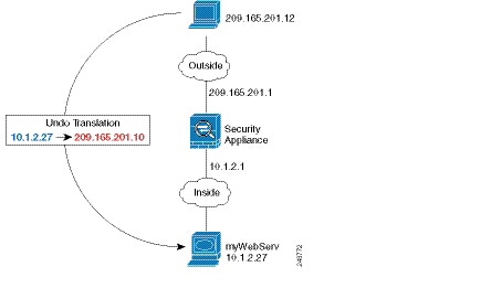
Figure 4-1 Static NAT for an Inside Web Server
Step 1 Create a network object for the internal web server:
ciscoasa(config)# object network myWebServ
Step 2 Define the web server address:
ciscoasa(config-network-object)# host 10.1.2.27
Step 3 Configure static NAT for the object:
ciscoasa(config-network-object)# nat (inside,outside) static 209.165.201.10
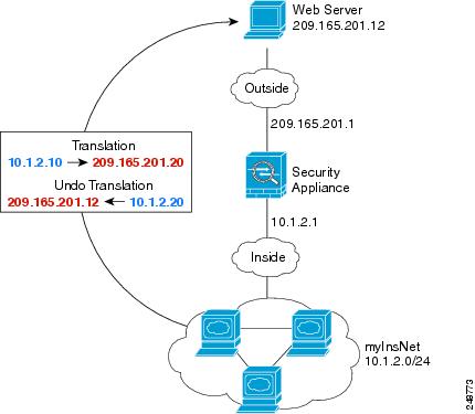
The following example configures dynamic NAT for inside users on a private network when they access the outside. Also, when inside users connect to an outside web server, that web server address is translated to an address that appears to be on the inside network. (See Figure 4-2).
Figure 4-2 Dynamic NAT for Inside, Static NAT for Outside Web Server
Step 1 Create a network object for the dynamic NAT pool to which you want to translate the inside addresses:
ciscoasa(config)# object network myNatPool
ciscoasa(config-network-object)# range 209.165.201.20 209.165.201.30
Step 2 Create a network object for the inside network:
ciscoasa(config)# object network myInsNet
ciscoasa(config-network-object)# subnet 10.1.2.0 255.255.255.0
Step 3 Enable dynamic NAT for the inside network:
ciscoasa(config-network-object)# nat (inside,outside) dynamic myNatPool
Step 4 Create a network object for the outside web server:
Step 5 Define the web server address:
ciscoasa(config-network-object)# host 209.165.201.12
Step 6 Configure static NAT for the web server:
ciscoasa(config-network-object)# nat (outside,inside) static 10.1.2.20
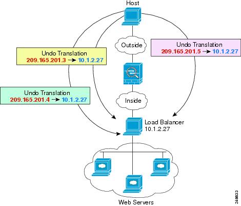
The following example shows an inside load balancer that is translated to multiple IP addresses. When an outside host accesses one of the mapped IP addresses, it is untranslated to the single load balancer address. Depending on the URL requested, it redirects traffic to the correct web server. (See Figure 4-3).
Figure 4-3 Static NAT with One-to-Many for an Inside Load Balancer
Step 1 Create a network object for the addresses to which you want to map the load balancer:
ciscoasa(config)# object network myPublicIPs
ciscoasa(config-network-object)# range 209.165.201.3 209.265.201.8
Step 2 Create a network object for the load balancer:
ciscoasa(config)# object network myLBHost
Step 3 Define the load balancer address:
Step 4 Configure static NAT for the load balancer:
ciscoasa(config-network-object)# nat (inside,outside) static myPublicIPs
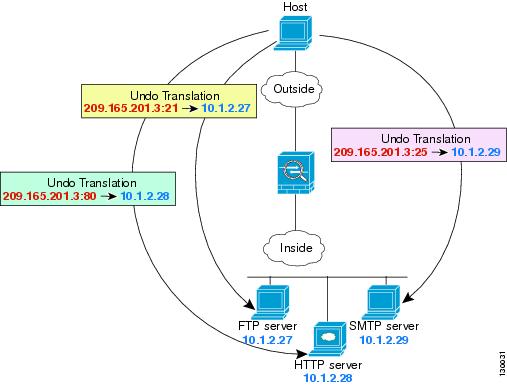
The following static NAT-with-port-translation example provides a single address for remote users to access FTP, HTTP, and SMTP. These servers are actually different devices on the real network, but for each server, you can specify static NAT-with-port-translation rules that use the same mapped IP address, but different ports. (See Figure 4-4.)
Figure 4-4 Static NAT-with-Port-Translation
Step 1 Create a network object for the FTP server address:
ciscoasa(config)# object network FTP_SERVER
Step 2 Define the FTP server address, and configure static NAT with identity port translation for the FTP server:
ciscoasa(config-network-object)# nat (inside,outside) static 209.165.201.3 service tcp ftp ftp
Step 3 Create a network object for the HTTP server address:
ciscoasa(config)# object network HTTP_SERVER
Step 4 Define the HTTP server address, and configure static NAT with identity port translation for the HTTP server:
ciscoasa(config-network-object)# host 10.1.2.28
ciscoasa(config-network-object)# nat (inside,outside) static 209.165.201.3 service tcp http http
Step 5 Create a network object for the SMTP server address:
ciscoasa(config)# object network SMTP_SERVER
Step 6 Define the SMTP server address, and configure static NAT with identity port translation for the SMTP server:
ciscoasa(config-network-object)# host 10.1.2.29
ciscoasa(config-network-object)# nat (inside,outside) static 209.165.201.3 service tcp smtp smtp
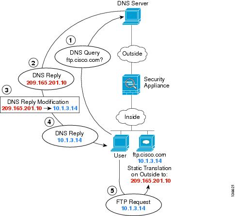
For example, a DNS server is accessible from the outside interface. A server, ftp.cisco.com, is on the inside interface. You configure the ASA to statically translate the ftp.cisco.com real address (10.1.3.14) to a mapped address (209.165.201.10) that is visible on the outside network. (See Figure 4-5.) In this case, you want to enable DNS reply modification on this static rule so that inside users who have access to ftp.cisco.com using the real address receive the real address from the DNS server, and not the mapped address.
When an inside host sends a DNS request for the address of ftp.cisco.com, the DNS server replies with the mapped address (209.165.201.10). The ASA refers to the static rule for the inside server and translates the address inside the DNS reply to 10.1.3.14. If you do not enable DNS reply modification, then the inside host attempts to send traffic to 209.165.201.10 instead of accessing ftp.cisco.com directly.
Figure 4-5 DNS Reply Modification
Step 2 Define the FTP server address, and configure static NAT with DNS modification:
ciscoasa(config-network-object)# host 10.1.3.14
ciscoasa(config-network-object)# nat (inside,outside) static 209.165.201.10 dns
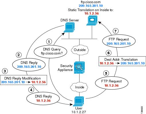
Figure 4-6 shows an FTP server and DNS server on the outside. The ASA has a static translation for the outside server. In this case, when an inside user requests the address for ftp.cisco.com from the DNS server, the DNS server responds with the real address, 209.165.201.10. Because you want inside users to use the mapped address for ftp.cisco.com (10.1.2.56) you need to configure DNS reply modification for the static translation.
Figure 4-6 DNS Reply Modification Using Outside NAT
ciscoasa(config-network-object)# host 209.165.201.10
ciscoasa(config-network-object)# nat (outside,inside) static 10.1.2.56 dns
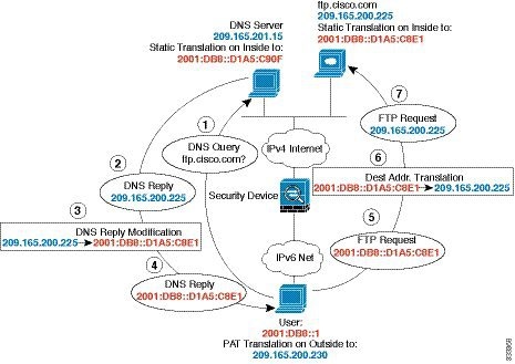
Figure 4-6 shows an FTP server and DNS server on the outside IPv4 network. The ASA has a static translation for the outside server. In this case, when an inside IPv6 user requests the address for ftp.cisco.com from the DNS server, the DNS server responds with the real address, 209.165.200.225. Because you want inside users to use the mapped address for ftp.cisco.com (2001:DB8::D1A5:C8E1) you need to configure DNS reply modification for the static translation. This example also includes a static NAT translation for the DNS server, and a PAT rule for the inside IPv6 hosts.
Figure 4-7 DNS Reply Modification Using Outside NAT
Step 1 Configure static NAT with DNS modification for the FTP server.
a. Create a network object for the FTP server address.
b. Define the FTP server address, and configure static NAT with DNS modification and, because this is a one-to-one translation, configure the net-to-net method for NAT46.
ciscoasa(config-network-object)# host 209.165.200.225
ciscoasa(config-network-object)# nat (outside,inside) static 2001:DB8::D1A5:C8E1/128 net-to-net dns
Step 2 Configure NAT for the DNS server.
a. Create a network object for the DNS server address.
ciscoasa(config)# object network DNS_SERVER
b. Define the DNS server address, and configure static NAT using the net-to-net method.
ciscoasa(config-network-object)# host 209.165.201.15
ciscoasa(config-network-object)# nat (outside,inside) static 2001:DB8::D1A5:C90F/128 net-to-net
Step 3 Configure an IPv4 PAT pool for translating the inside IPv6 network.
Step 4 Configure PAT for the inside IPv6 network.
a. Create a network object for the inside IPv6 network.
b. Define the IPv6 network address, and configure dynamic NAT using a PAT pool.
Table 4-1 lists each feature change and the platform release in which it was implemented.
Platform Releases
Feature Information
Network Object NAT
8.3(1)
Configures NAT for a network object IP address(es).
We introduced or modified the following commands: nat (object network configuration mode), show nat , show xlate , show nat pool .
Identity NAT configurable proxy ARP and route lookup
8.4(2)/8.5(1)
In earlier releases for identity NAT, proxy ARP was disabled, and a route lookup was always used to determine the egress interface. You could not configure these settings. In 8.4(2) and later, the default behavior for identity NAT was changed to match the behavior of other static NAT configurations: proxy ARP is enabled, and the NAT configuration determines the egress interface (if specified) by default. You can leave these settings as is, or you can enable or disable them discretely. Note that you can now also disable proxy ARP for regular static NAT.
When upgrading to 8.4(2) from 8.3(1), 8.3(2), and 8.4(1), all identity NAT configurations will now include the no-proxy-arp and route-lookup keywords, to maintain existing functionality.
We modified the following command: nat static [ no-proxy-arp ] [ route-lookup ].
PAT pool and round robin address assignment
You can now specify a pool of PAT addresses instead of a single address. You can also optionally enable round-robin assignment of PAT addresses instead of first using all ports on a PAT address before using the next address in the pool. These features help prevent a large number of connections from a single PAT address from appearing to be part of a DoS attack and makes configuration of large numbers of PAT addresses easy.
We modifed the following command: nat dynamic [ pat-pool mapped_object [ round-robin ]].
Round robin PAT pool allocation uses the same IP address for existing hosts
8.4(3)
When using a PAT pool with round robin allocation, if a host has an existing connection, then subsequent connections from that host will use the same PAT IP address if ports are available.
We did not modify any commands.
This feature is not available in 8.5(1) or 8.6(1).
Flat range of PAT ports for a PAT pool
If available, the real source port number is used for the mapped port. However, if the real port is not available, by default the mapped ports are chosen from the same range of ports as the real port number: 0 to 511, 512 to 1023, and 1024 to 65535. Therefore, ports below 1024 have only a small PAT pool.
If you have a lot of traffic that uses the lower port ranges, when using a PAT pool, you can now specify a flat range of ports to be used instead of the three unequal-sized tiers: either 1024 to 65535, or 1 to 65535.
We modifed the following command: nat dynamic [ pat-pool mapped_object [ flat [ include-reserve ]]].
Extended PAT for a PAT pool
Each PAT IP address allows up to 65535 ports. If 65535 ports do not provide enough translations, you can now enable extended PAT for a PAT pool. Extended PAT uses 65535 ports per service , as opposed to per IP address, by including the destination address and port in the translation information.
We modifed the following command: nat dynamic [ pat-pool mapped_object [ extended ]].
Automatic NAT rules to translate a VPN peer’s local IP address back to the peer’s real IP address
In rare situations, you might want to use a VPN peer’s real IP address on the inside network instead of an assigned local IP address. Normally with VPN, the peer is given an assigned local IP address to access the inside network. However, you might want to translate the local IP address back to the peer’s real public IP address if, for example, your inside servers and network security is based on the peer’s real IP address.
You can enable this feature on one interface per tunnel group. Object NAT rules are dynamically added and deleted when the VPN session is established or disconnected. You can view the rules using the show nat command.
Note Because of routing issues, we do not recommend using this feature unless you know you need this feature; contact Cisco TAC to confirm feature compatibility with your network. See the following limitations:
NAT support for IPv6
9.0(1)
NAT now supports IPv6 traffic, as well as translating between IPv4 and IPv6. Translating between IPv4 and IPv6 is not supported in transparent mode.
We modified the following commands: nat (object network configuration mode), show nat , show nat pool , show xlate .
NAT support for reverse DNS lookups
NAT now supports translation of the DNS PTR record for reverse DNS lookups when using IPv4 NAT, IPv6 NAT, and NAT64 with DNS inspection enabled for the NAT rule.
Per-session PAT
The per-session PAT feature improves the scalability of PAT and, for clustering, allows each member unit to own PAT connections; multi-session PAT connections have to be forwarded to and owned by the master unit. At the end of a per-session PAT session, the ASA sends a reset and immediately removes the xlate. This reset causes the end node to immediately release the connection, avoiding the TIME_WAIT state. Multi-session PAT, on the other hand, uses the PAT timeout, by default 30 seconds. For “hit-and-run” traffic, such as HTTP or HTTPS, the per-session feature can dramatically increase the connection rate supported by one address. Without the per-session feature, the maximum connection rate for one address for an IP protocol is approximately 2000 per second. With the per-session feature, the connection rate for one address for an IP protocol is 65535/ average-lifetime .
By default, all TCP traffic and UDP DNS traffic use a per-session PAT xlate. For traffic that requires multi-session PAT, such as H.323, SIP, or Skinny, you can disable per-session PAT by creating a per-session deny rule.
We introduced the following commands: xlate per-session , show nat pool .
We introduced the following command: nat-assigned-to-public-ip interface (tunnel-group general-attributes configuration mode).